Litz Wire Tech Tips
Litz Wire
The word “Litz” is derived from the German word “Litzendraht” and refers to wire consisting of a number of separately-insulated strands woven or bunched together such that each strand tends to take all possible positions in the cross-section of the entire conductor. This design concept results in equalizing the flux linkages and, hence reactances, of the individual strands, thereby causing the current to divide uniformly between strands. The resistance ratio (AC to DC) then tends to approach unity, which is desirable in all high Q circuit applications. Typical applications for Litz conductors include high frequency inductors and transformers, inverters, communication equipment, ultrasonic equipment, sonar equipment, television equipment, radio equipment and heat induction equipment.
By definition, Litz constructions are made with individually-insulated strands. Common magnet wire film insulations such as Formvar, Sodereze® (Polyurethane), Nyleze®, Thermaleze T®, Armored Poly-Thermaleze 2000®, and ML are normally used.1 The outer insulation and the insulation on the component conductors, in some styles, may be servings or braids of Nylon®, cotton, Nomex®, fiberglass or ceramic. Heat- sealed polyester, rubber, vinyl and Teflon® tape wraps along with most thermoplastic insulations are also available as outer insulations if the applications dictate special requirements for voltage breakdown or environmental protection.2
Litz Design
Typically, the design engineer requiring the use of Litz knows the operating frequency and RMS current required for his application. Since the primary benefit of a Litz conductor is the reduction of AC losses, the first consideration in any Litz design is the operating frequency. The operating frequency not only influences to some extent the actual Litz construction, but it is also used to determine the individual wire gauge.
Ratios of alternating-current resistance to direct-current resistance for an isolated solid round wire (H) in terms of a value (X) are shown in Figure 1.
The value of X for copper wire is determined by the following formula:

Where: DM = Wire diameter in mils
FMHZ = frequency in megahertz
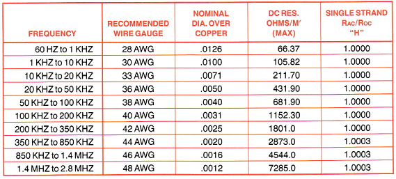
From Figure 1 and other empirical data, the table shown in Figure 2 of recommended wire gauges vs. frequency for most Litz constructions has been prepared.
After the individual wire gauge has been determined, and assuming that the Litz construction has been designed such that each strand tends to occupy all possible positions in the cable to approximately the same extent, the ratio of AC to DC resistance of an isolated Litz conductor can be determined from Formula (2):
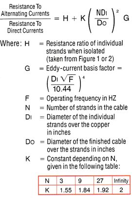
Figure 1

Figure 2
The DC resistance of a Litz conductor is related to the following parameters:
- AWG of the individual strands
- Number of strands in the cable
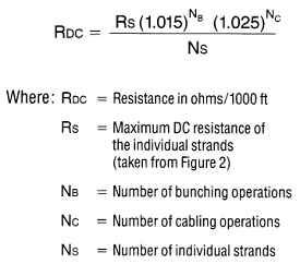
- Factors relating to the increased length of the individual strands per unit length of cable (take-up). For normal Litz constructions a 1.5% increase in DC resistance for every bunching operation and a 2.5% increase in DC resistance for every cabling operation is approximately correct.
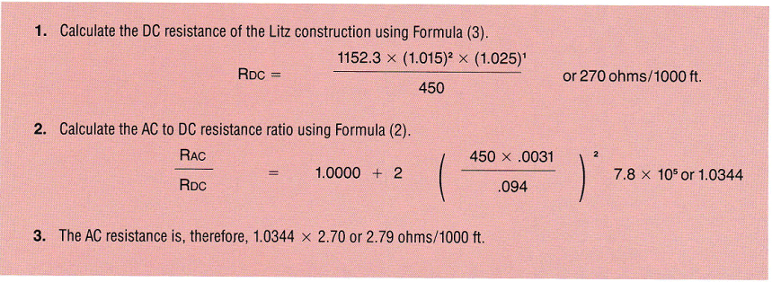
Formula (3) derived from these parameters for the DC resistance of any Litz construction is:
An example of the calculations required to evaluate a Type 2 Litz construction consisting of 450 strands of 40 AWG single polyurethane operating at 100 KHZ and designed with two bunching operations and one cabling operation is given in Figure 3.
The value of Litz can easily be seen if the example in Figure 3 is compared with a solid round wire 94 mils in diameter. Using the same operating parameters, the DC resistance is 1.197 ohms/M’. However, the AC/DC resistance ratio increases to approximately 3.1 making the AC resitance 9.6 ohms/1000 ft.
Figure 3
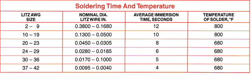
Soldering Of Litz Wire
The soldering stroke (immersion dip) should be a smooth, deliberate, and continuous, unhurried movement. The downward movement as the Litz wire enters the solder should be slow and encompass a horizontal movement that is parallel to or in the plane of the solder bath.
As the Litz wire is immersed into the solder, the film coating is removed, and oxides (contamination) are left on the surface of the solder pot due to the high surface tension effect of molten solder. The horizontal movement as discussed above allows the oxide contamination to be left behind the wire.
When soldering Litz wire, we recommend a pause at mid-pot to allow the heat to penetrate from strand to strand for the film and oxide on each to be reduced to a liquid residue, floated off, and then replaced with solder. Pause times must be determined experimentally.
Last, and the most important, is to skim the molten solder surface at adequate intervals with a piece of sheet metal or cardboard to prevent oxides from the film and any surface oxidation from adherence to the soldered Litz.
1 Sodereze®, Nyleze®, Thermaleze®, and Armored Poly-Thermaleze
2000® are registered trademarks of the Phelps Dodge Corporation.
2 Nylon®, Nomex®, and Teflon® are registered trademarks of The DuPont Company.
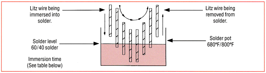
Figure 4