Nichrome Wire Tech Tips
HEATING ELEMENT CALCULATIONS
BASIC DESIGN FORMULAS
To make the basic calculations for the design of heating elements, the following formulas, known as Ohm’s Law, are essential:
- Volts = Amperes X Ohms E = I x R
- Watts = Volts X Amperes W = E x I
- Watts = (Amperes)2 X Ohms W = I2 x R
USEFUL COIL FORMULAS
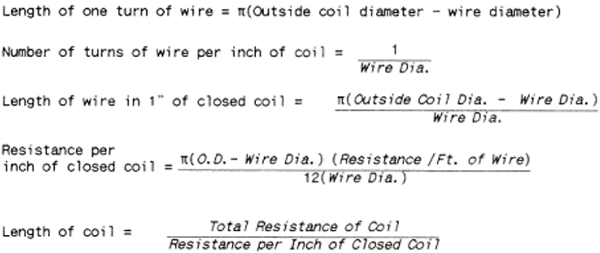
COMBINING THE FORMULAS GIVEN ABOVE WE GET THE COMPLETE FORMULA FOR COIL CALCULATIONS.
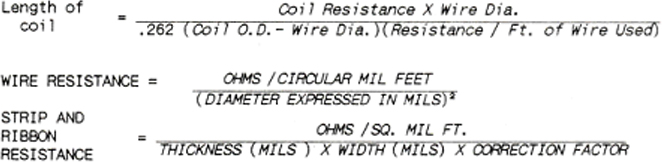
If calculations are done for ribbon wire, a correction factor of .94 or .83 must be used depending on the ratio of width to thickness. The higher the width to thickness ratio the lower the correction factor.
COILED ELEMENT DESIGN
Suppose a coil is to be designed to fit a ceramic hot plate spiral
We know that:
- We want an 800-watt element
- The groove is 30” long and ¼” wide.
- The element is to operate on 115 volts.
- To insure the best possible life, we will use NICHROME 80.
To find total cold coil resistance:
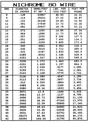
Table I shows that for NICHROME 80 we need 15.44 ohms in the coil and the recommended wire gauges are #18 to #22.
To select coil diameter and wire gauge:
The heavier the wire selected the lower will be the final operating temperature of the element itself, but the wattage input will determine the heat delivered. For the present element let us select #20 gauge wire. Looking in Table II we find the resistance per inch of close would coil for 7/32” dia. (thus allowing 1/32” clearance in the ¼” groove) #20 gauge. The resistance is .967 ohms per inch.
Length of coil and stretch factor:
We now know that we need a total coil resistance of 15.44 ohms and a resistance per inch of .967 ohms thus 15.44/.967 = 16” of closed coil. This would mean a stretch factor of 30/15 or 2:1. A stretched coil should be 1.5 to 4 times its closed length for good design.
Other calculations on this coil might be:
Estimated wire temperature:
Can be found in Table III.
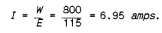
We are using #20 gauge wire and can calculate that the current will be:
Looking across the table we find the coil temperature in air will be about 1300° F. When surrounded by the ceramic this temperature would probably be about 200° F. higher or about 1500° F.
Watts per square inch of element surface:
One method used to test the soundness of an element design is a check on the power density per square inch of radiant surface. This is done in the following manner:
Our element is to be constructed of #20 gauge wire (.032” dia.) with a total resistance of 15.44 ohms. From Table V we find that .032” NICHROME 80 has a resistance of .6347 ohms per foot. Thus, the total length of wire equals Total ohms/ Ohms per Foot of Wire.
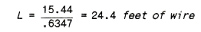
The surface area of the element is:
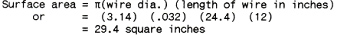

For safe design the watts density on an open helical coil should not exceed 35 watts per square inch when the element is operated in still air. Naturally, if the coil is to be used to heat a rapidly moving air stream, the power density may be safely increased. Conversely, if the coil is to be imbedded in a refractory material, the power density must be decreased to prevent overheating of the element.
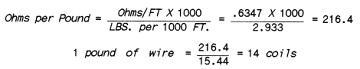
Number of coils per pound of wire:
Using #20 gauge wire with 15.44 ohms per coil, from Table V we find that there are .6347 ohms per foot of wire, thus
RIBBON ELEMENT DESIGN
Suppose a ribbon wound mica element is to be designed for a single piece toaster.
We know that:
- We want 500 watts.
- The element will operate on 115 volts.
- The mica sheet has space for 10 feet of ribbon. Again we will use NICHROME 80.
To find the cold ribbon resistance:
Table I shows that for NICHROME 80 we need 24.704 ohms of cold resistance.
As we need 10’ of ribbon this means a resistance per foot of: 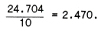
To estimate ribbon size:
From the ribbon resistance for NICHROME 80 in Table IV we find that 1/16 x .004 ribbon has a resistance of 2.458 ohms per foot which should work very well and wrap easily on the mica form.
To make an approximate check on the soundness of our element design e\we should
calculate the watts density per square inch of element surface.
Our ribbon is 120 inches long, 1/16 inch wide and .004” thick. Therefore, the total surface area is:
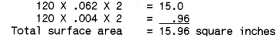
The watts density is thus:
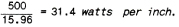
For approximate design calculations the following table gives the range of watts per square inch for various types of elements:
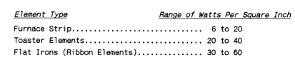
It should be pointed out that the matter of watts per square inch is a factor which varies considerably due to design characteristics of the unit. In general, the better a means is provided for heat conduction from the element the higher is the safe limit of power density. This is especially true for electric irons where, due to close contact, the sole plate can be considered the radiating surface.
TABLE I
Size and Approximate Cold Resistances of Various Alloys for Common Wattages
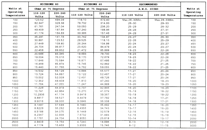
TABLE II
Ohms Per Inch of Closed Helix
NICHROME 80
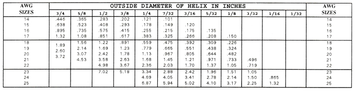
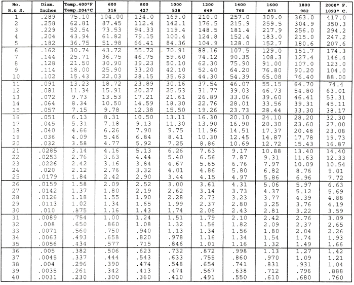
TABLE III
CURRENT TEMPERATURE CHARACTERISTICS OF
NICHROME 80
HELICAL COILS
These data have been compiled as an aid to the manufacturers of helical coils and show the approximate current in amperes required to heat the coils in open air to the indicated temperatures under the conditions specified
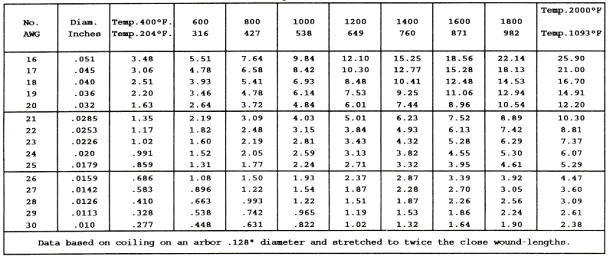
TABLE IV
RESISTANCE OF
NICHROME 80 RIBBON
In Ohms per Foot at 68° F. (20° C.)
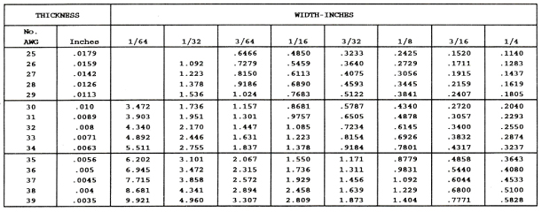
TABLE V
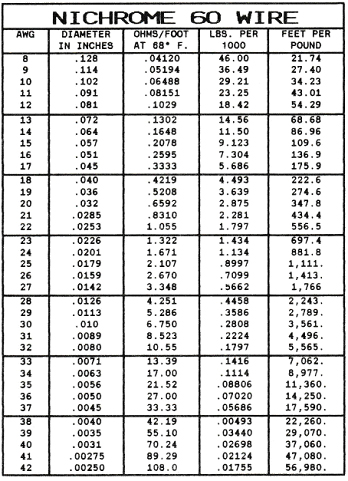
CURRENT TEMPERATURE CHARACTERISTICS OF NICHROME 60
STRAIGHT WIRE
Showing approximate amperes necessary to produce a given temperature. Applying only to straight wires stretched horizontally in free air.